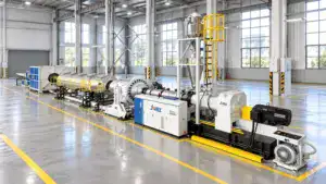
In plastic sheet extrusion troubleshooting, periodic transverse lines do not automatically mean that the screw is worn or out of alignment. The mark may be copied onto the sheet by the downstream calender, created by unstable tension between the die and haul-off, or caused by high shear at the die lip. Measure the line spacing first, then check each zone against a machine signal before dismantling the screw.
Start With the Pattern, Not the Screw
The shape and spacing of the defect provide the first diagnosis. Record the distance between several consecutive lines, then compare the spacing with line speed, roll speed, and pressure trends.
| What you see on the sheet | Most likely zone | First check |
| Very regular lines with nearly constant spacing | Roll drive, gear mesh, chain, or bearing | Measure spacing and compare it with roll or gear frequency |
| Bands that become wider or narrower when line speed changes | Speed mismatch or tension instability | Compare die output, roll speed, and haul-off speed |
| Fine, dense waves with a dull or rough surface | High shear or melt fracture | Check die-lip temperature, output, and die condition |
| Local thermoforming cracks in the same machine direction | Gauge variation or an overheated/thin area | Map thickness and review the heating window |
This pattern-first approach is especially useful on a complete sheet extrusion line, where the defect may be introduced after the melt leaves the die.
Check the Three-Roll Calender for Mechanical Vibration
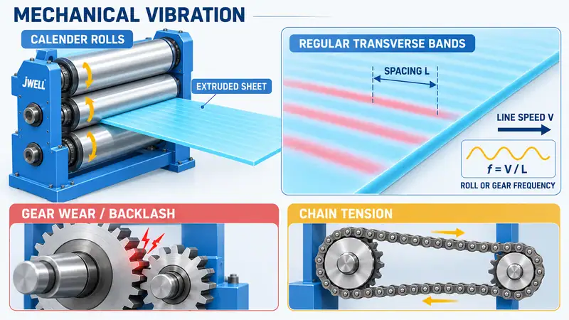
The three-roll or multi-roll calender controls cooling, thickness, and surface replication. If the transverse lines are highly regular, inspect the roll drive before changing resin or pulling the screw.
Start with the reducer and roll-coupling gears. Local tooth wear, a damaged tooth, excessive backlash, or poor gear engagement can create a small impact once per revolution or once per mesh cycle. The roll surface then transfers that small periodic movement to sheet that has not fully solidified.
Chain drives need the same attention. A loose chain can slip and oscillate; an over-tight chain can impose a repeating pull on the roll shaft. Inspect chain tension, sprocket wear, bearing condition, coupling alignment, and the roll-support frame. Use a non-contact vibration meter where possible. Never place a hand near moving rolls or an exposed chain; isolate and lock out the equipment before any manual inspection.
You can estimate the vibration frequency from the sheet itself:
f = V / L
Here, f is the defect frequency, V is sheet line speed, and L is the measured distance between two repeated lines. If the calculated frequency matches a roll rotation, gear-mesh, or chain event, the mechanical diagnosis becomes much stronger.
Match Die Output, Roll Speed, and Haul-Off Tension
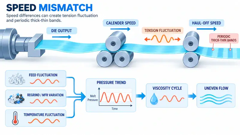
Not every transverse line is a vibration mark. A sheet can also show periodic thick and thin bands when the melt is alternately stretched and released between the die, calender, and haul-off.
The first check is the relationship between melt delivery and downstream speed. If the rolls or haul-off pull faster than the melt can supply, the sheet is drawn thin; when the pull relaxes, it becomes thicker again. This tension cycle can appear even when the gears are healthy.
Trend the following values together rather than reading them one at a time:
- Extruder output or screw speed
- Die pressure and melt temperature
- Calender and haul-off speed
- Measured sheet thickness
Pressure that rises and falls at a regular interval points to an unstable feed or melting condition. Check regrind percentage, melt-flow-rate differences between batches, bridging or starvation at the feed throat, and heater-band or thermocouple connections. A large change in recycled material or resin melt flow can change viscosity enough to disturb die flow. Stabilize the feed and temperature profile before increasing output.
Nameplate output is not saleable output; resin grade, gauge, cooling capacity, and downstream tension define the stable window.
Rule Out High Shear and Melt Fracture
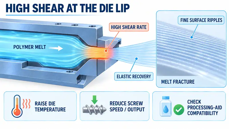
Fine, closely spaced waves with a darker, rougher, or hazy surface can indicate melt fracture. Melt fracture is a surface instability that occurs when the local shear rate at the die lip exceeds what the polymer and tool geometry can accommodate. The polymer elastically recovers as it exits the die, leaving a repeating rough pattern.
This condition is different from a gear vibration. It normally becomes more visible as output or screw speed increases, and it can improve when the melt becomes less viscous. Inspect the die lip for deposits, damage, or an unsuitable land condition. Then make one controlled adjustment at a time:
- Raise the die and lip temperature in a small trial, such as 5-10°C, only within the resin and tooling limits.
- Reduce screw speed or output if the production target allows it.
- Confirm that screens, flow channels, and the die are clean and correctly assembled.
- Consider a compatible polymer-processing aid or internal lubricant only after material, food-contact, recycling, and customer requirements have been reviewed.
If a temperature increase reduces the lines while mechanical vibration remains unchanged, the evidence favors a flow or shear problem. An additive will not correct a damaged die, unstable feed, or excessive drawdown.
Use a Safe Field Troubleshooting Sequence
Capture evidence before making several adjustments at once.
- Measure the pattern.Record at least five line spacings, line speed, width, thickness, resin grade, and output. Use the frequency formula above.
- Change speed briefly.Check whether spacing widens in proportion to speed, remains random, or disappears.
- Compare trends and inspect safely.Overlay pressure, melt temperature, screw speed, calender speed, and haul-off speed. Use vibration measurement first; if close inspection is necessary, follow lockout procedures.
- Run one controlled trial.Adjust die-lip temperature or output, then map thickness across the width and along the machine direction.
Keep a before-and-after sample for each trial. A smoother surface is not a finished solution if thickness or forming behavior shifts.
Why the Same Defect Can Cause Thermoforming Cracks
Periodic lines can be associated with local thermoforming rupture when they also create gauge variation. A thin band heats faster, stretches more, and can concentrate strain during vacuum forming. Confirm the link with a thickness map and forming trial; also check sheet temperature, heating time, plug assist, vacuum timing, and final wall thickness.
When to Involve the Line Supplier
Escalate when the pattern remains after mechanical checks, speed tests, and a stable temperature trial. Keep the resin, line, and defect data ready so the supplier can separate equipment behavior from material or forming conditions.
For a line-specific review, compare your measurements with the configuration of the selected PP/PS sheet extrusion line. Product pages show a reference configuration, but the correct die, calender, cooling, and control settings depend on the material and target gauge.
FAQ
Is a periodic transverse line always caused by screw wear?
No. Regular spacing often points to a roll-drive or chain frequency; pressure instability and die shear are other common causes. Check those zones before removing the screw.
How can I separate mechanical vibration from melt fracture?
Measure spacing and change line speed briefly. Spacing that follows roll or gear frequency supports a mechanical cause; fine roughness that responds to die temperature or output supports melt fracture.
Can raising the die temperature remove the lines?
It can reduce shear-related roughness by lowering melt viscosity, but it will not repair a worn gear, loose chain, or unstable feed. Use a controlled 5-10°C trial within resin and die limits, then confirm thickness.
Discuss Your Sheet Extrusion Process
Periodic transverse lines are easier to solve when the process data travels with the sheet sample. Send JWELL your material and melt-flow data, target width and thickness, line speed, output, operating hours, pressure and temperature trends, defect spacing, photos, and any thermoforming failure samples. Our engineers can use this information to review the process window, downstream configuration, and next troubleshooting step. Contact JWELL to start the discussion.